


How to Remove Dental Miniature Bearings with Bearing Puller

Jun
Technical Guide: Removing Outer Shields from Micro Bearings in Dental Equipment
World’s best-known brands like KaVo, Sirona, NSK, W&H assemble their High Speed Dental Turbines with Premium quality ceramic bearings with size 3.175 x 6.35 x 1.9–2.78mm, and usually Contra Angle handpieces are assembled with steel bearings with size 4 x 7 x 2mm.
To make service for these dental handpieces, you must extract the rotor/cartridge or head gears on Contra Angles from the head, but because the bearing breaks a lot of time external shield of the bearings remains, stays blocked in the head, and it’s very hard to extract with usual instruments.
In most cases, these external parts of the bearing shield can be extracted with dental excavators, but sometimes these bearings can break because they are dropped and get stuck there, making them very hard to extract.
For this case, you must use a bearing puller for micro/ miniature bearings
This technical guide provides comprehensive instructions for safely removing outer shields from these delicate micro bearings.
Understanding Micro Bearing Construction
Before attempting shield removal, it’s essential to understand the construction of these precision bearings. Dental micro bearings typically feature:
- Inner race: Fixed to the rotating shaft
- Outer race: Housed within the handpiece body
- Ball bearings: Usually ceramic or steel, providing smooth rotation
- Cage/retainer: Maintains proper ball spacing
- Shields: Protect internal components from contamination
- Seals: Additional protection in some models
The outer shield is typically a thin metal disc that fits into a groove on the outer race. It may be press-fitted or held by a retaining ring, depending on the manufacturer and bearing design.
Read here about Stepped Bearings vs. Stepped Integral Shield Bearings, High-Speed Bearings
Small Bearing Puller Sets: Essential Tools for Precision Work
A small bearing puller set is an indispensable tool collection specifically designed for working with micro bearings in dental equipment. These specialized tool sets typically include:

Components of a quality small bearing puller set:
- Multiple jaw sizes (typically 2-jaw and 3-jaw configurations)
- Adjustable puller arms with fine thread adjustment
- Precision-ground jaw tips to prevent bearing damage
- Central forcing screw with knurled handle
- Various adapter plates and spacers
- Bearing separator plates in multiple sizes
- Push-pull attachments for different bearing configurations
Material specifications: Professional-grade puller sets are manufactured from hardened tool steel with precisely machined surfaces. The jaw tips often feature a special coating or heat treatment to prevent marring of bearing surfaces. The forcing screws incorporate fine-pitch threads for controlled, gradual pressure application, which is critical when working with delicate micro bearings.
How Small Bearing Pullers Work: The Mechanical Process
Understanding the mechanical principles behind bearing pullers is crucial for effective shield removal. The process involves controlled force application through leverage and mechanical advantage.
Basic operating principle: The puller works by gripping the component to be removed (in this case, the outer shield) while applying opposing force through a central screw mechanism. The jaws are positioned to contact the shield’s outer edge, while the central screw bears against a stable reference point, typically the inner race or a specially designed adapter.
Force distribution: When the central screw is turned, it creates a pulling force that is evenly distributed through the puller arms to the jaws. This controlled application prevents sudden force spikes that could damage the bearing components. The mechanical advantage provided by the screw thread allows for precise control and gradual removal.
Critical alignment factors: Proper jaw alignment is essential to prevent binding or uneven force application. The puller must be positioned so that the pulling force acts parallel to the bearing axis, avoiding side loads that could deform the shield or damage the bearing races.
Step-by-Step Shield Removal Process
Preparation Phase
- Clean the work area and ensure adequate lighting for precision work
- Secure the bearing in a proper holding fixture or soft-jaw vise
- Inspect the bearing for any visible damage or unusual wear patterns
- Select the appropriate puller size based on bearing dimensions
- Apply light penetrating oil around the shield perimeter if corrosion is present
Shield Removal Procedure
- Position the bearing with the shield to be removed facing upward
- Install the puller jaws, ensuring they contact only the shield’s outer edge
- Check jaw alignment – all contact points should be equidistant fromthe center
- Apply initial light pressure by hand-turning the central screw
- Verify proper engagement before applying significant force
- Turn the forcing screw gradually – typically 1/4 turn increments
- Monitor for movement and listen for any unusual sounds
- Continue gradual pressure until the shield separates from the bearing
- Remove the puller and carefully extract the shield
Critical Safety Points
- Never apply sudden or excessive force
- Stop immediately if binding occurs
- Use proper eye protection
- Ensure work surface stability
- Maintain clean hands and tools throughout the process
Removing Broken Bearings: Advanced Techniques
When dealing with broken or seized bearings, standard removal techniques may not be sufficient. Broken bearings present unique challenges that require specialized approaches and additional precautions.
Assessment of damage: Before attempting removal, carefully evaluate the extent of bearing damage. Determine whether the inner race, outer race, or both components are compromised. Take note of any visible cracks, missing ball bearings, or deformed races that might complicate the removal process.
Modified puller techniques: For broken bearings, conventional puller jaw placement may not be possible. In these cases, use bearing separator plates that can be inserted between the bearing and its housing. The separator plate provides a purchase point for the puller jaws while protecting the housing from damage. Apply penetrating oil and allow it to penetrate before attempting removal.
Heat application considerations: In extreme cases, controlled heat application can help free seized bearings. Use a precision heat gun or bearing heater to warm the housing to approximately 200°F (93°C). The thermal expansion of the housing material will reduce the interference fit, making removal easier. Never use open flame or excessive heat, as this can damage seals and lubricants in adjacent components.
Alternative extraction methods: When conventional pullers fail, consider using bearing pullers with expanding internal grips. In some cases, the bearing may need to be carefully destroyed for removal, requiring subsequent housing inspection for damage.
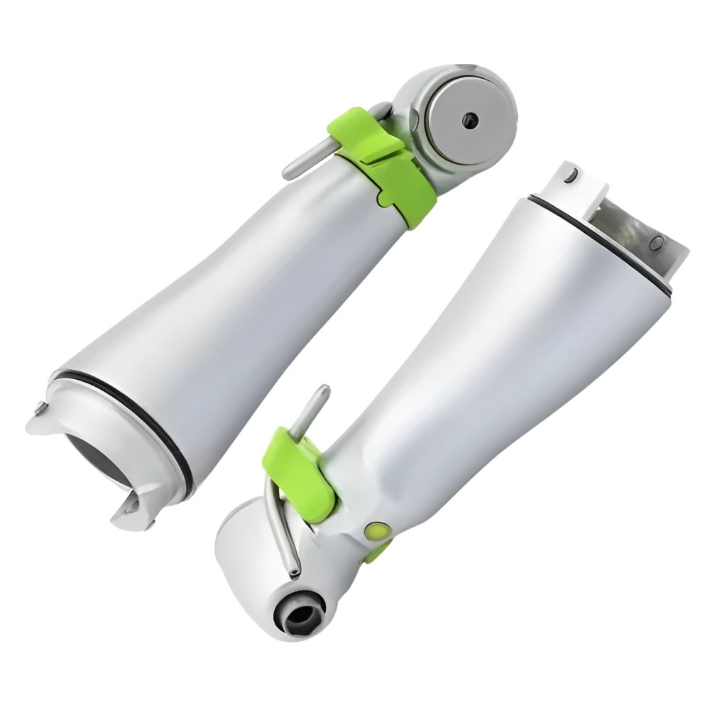
Removing Bearings from Dental Turbine Head
The turbine head represents the most critical and delicate area of dental handpiece maintenance. This component houses the high-speed bearings that enable rotational speeds exceeding 400,000 RPM.
Pre-removal inspection: Before beginning bearing removal from the turbine head, conduct a thorough visual inspection of the turbine assembly. Check for any signs of damage to the turbine rotor, housing threads, or air passages. Document the original bearing orientation and any spacer arrangements, as proper reassembly is critical for balanced operation.
Specialized tooling requirements: Turbine head bearing removal requires specialized fixtures designed specifically for dental handpieces. These fixtures support the turbine housing while providing access for bearing removal tools. The fixture must securely hold the component without inducing stress that could cause housing distortion.
Step-by-step turbine bearing removal:
- Secure the turbine head in the appropriate holding fixture
- Remove any retaining clips or threaded components that secure the bearing
- Apply a small amount of penetrating oil around the bearing perimeter
- Position the micro bearing puller with jaws contacting the bearing outer race
- Apply a gradual pulling force while monitoring for any housing distortion
- Once the bearing begins to move, maintain steady pressure until complete removal
- Clean the bearing seat thoroughly before installing replacement bearings
Critical considerations: The aluminum or titanium alloy construction of most turbine heads requires careful handling to prevent damage. These materials are softer than the bearing steel and can be easily damaged by improper tool use or excessive force.
Removing Bearings from Back Cap Assembly
The back cap of dental handpieces contains bearings that support the drive mechanism and provide stability for the rotating assembly. These bearings typically operate at lower speeds than turbine bearings but are equally important for proper handpiece function.
Back cap disassembly sequence: Begin by removing the back cap from the handpiece body according to manufacturer’s specifications. Most back caps are threaded and require specific torque values for proper installation, so note the original tightness for reassembly reference. Remove any O-rings or seals and set them aside in a clean, organized manner.
Bearing configuration analysis: Back cap bearings may be installed in various configurations, including single bearings, duplex pairs, or bearing sets with spacers. Carefully document the original arrangement before removal, as improper reassembly can result in preload issues or inadequate bearing life.
Removal procedure for back cap bearings:
- Support the back cap in a fixture that provides access from both sides
- Identify whether bearings are press-fitted or retained by clips
- For press-fitted bearings, use a bearing puller with arms positioned on the outer race
- Apply steady, controlled force while monitoring for proper movement
- If resistance is encountered, apply light penetrating oil and allow time for penetration
- Continue gradual pressure until the bearing is completely removed
- Inspect the bearing seat for any damage or contamination
Post-removal inspection: After bearing removal, thoroughly inspect the back cap for any signs of wear, corrosion, or damage. Pay particular attention to bearing seats, which should be smooth and free from scratches or dents. Any damage to bearing seats can result in improper bearing installation and premature failure. Any external shield parts of micro bearings can be extracted with the best micro bearing puller on the market.
Quality Control and Verification
Following any bearing removal procedure, implement quality control measures to ensure the work was completed properly and no damage occurred to surrounding components.
Component inspection checklist:
- Verify all bearing seats are clean and undamaged
- Check that the removal tools did not mar the housing surfaces
- Confirm proper torque specifications for reassembly
- Document any unusual findings or component wear patterns
- Test fit new bearings before final installation
Performance verification: After reassembly, conduct functional tests to verify proper operation. For turbine assemblies, this includes checking free-wheel spin time and listening for any unusual noises. Back cap assemblies should be tested for proper engagement and smooth operation throughout the full range of motion.
Conclusion
Proper removal of outer shields and bearings from dental equipment requires specialized knowledge, appropriate tooling, and careful technique. The precision nature of these micro bearings demands respect for tight tolerances and careful handling throughout the maintenance process. By following these established procedures and using quality tools, dental technicians can ensure reliable equipment performance and extended service life.
Regular maintenance and proper bearing care not only ensure optimal patient care but also represent sound economic practice through reduced equipment downtime and extended component life. Investment in proper tooling and training pays dividends in improved equipment reliability and reduced maintenance costs over the equipment’s operational lifetime.